SHOP
2 min read

How to Minimize Warpage in HP MJF Parts

By Mark Blumreiter on Mar 6, 2020 11:19:36 AM

The HP Multi Jet Fusion (MJF) printing process is similar to injection molding in a few ways. MJF and molding are both heat-based processes that melt raw plastic to form the final part shape. Because of this, there are similarities in how to properly design and prepare a part for each manufacturing process.

Just like injection molding, we want to control the heating and cooling in MJF printing to ensure good part quality. The MJF process uses a combination of lamps and thermal cameras to do this. By monitoring and controlling the heating/fusing and cooling process we can prevent or minimize defects like warpage.

Figure 1: HP MJF Printing Process

MJF Printing Process

Warpage

Warpage is a possible defect in any polymer process that involves heat. Warpage is especially common in long, thin, flat parts. (aspect ratio greater than 10:1) When plastic cools from molten to solid, it contracts to take up less space. When one area of a large flat part cools before another area, it can “pull” the part towards it. With small compact parts (as opposed to long thin parts) it is much easier to control the cooling and prevent warpage.

warpage b

For large, thin, flat parts, we recommend placing the parts parallel to the X-Y plane. This causes the part to melt and cool at a consistent rate. To further prevent warpage, align the length of the part in the Y-axis. The lamp carriage moves in the X-axis, so it will fuse the entire part at once when it move across. Along these same lines, try to avoid fast cooling if warpage is an issue. This allows the parts to naturally cool while they’re “held in place” by the surrounding powder.

Parts placed in the center of the build volume towards the bottom will be the least prone to warpage. This is because it will cool the most uniformly (from the outside in)

Figure 2: Avoid warpage by placing parts flat in the center-bottom of the build area

build

Design Changes

If that still doesn’t work, we have a few more options. One, we could print other parts, or even sacrificial parts, surrounding this large one. This, in effect, cages in the bigger part to hold the heat in and also slows down the cooling so it’s nice and uniform. Just like injection molding, we can’t let one area cool faster than another or it will warp. The other option is to add some ribs or supporting geometry to your part to prevent warping. Depending on your application this may or may not be possible. You can design in support bars to keep a part aligned while it cools, then snip the alignment bars off. This is similar to trimming the plastic from the gate in a molding process.

Material Considerations

PA11 will be most susceptible to warpage. If flatness is a major concern, we recommend using PA12 or PA12 with glass beads. If PA11 is necessary, use the Fast print mode. Regardless of which material is used, the HP MJF parts are usually flexible enough to easily be re-shaped or pushed into their final mounting position.

Keep these best practices in mind when designing and preparing your MJF prints, and you should be able to eliminate or at least minimize warpage in your parts.

Topics: 3D Printing
2 min read

Why is additive manufacturing unstoppable?

By Jim Hill on Feb 10, 2020 2:42:14 PM

As additive manufacturing technologies have advanced, 3D printed parts have moved decidedly outside the Research and Development arena and onto the production line. These pivotal processes are developing and producing concepts previously unattainable in the manufacturing world.

Entrepreneurs to Fortune 500 companies and large OEM’s have embraced the advanced enterprise of 3D printing to meet their tough performance standards and requirements. As companies have designed for additive manufacturing and utilized it as a compliment to traditional manufacturing, new applications have come to the scene and changed what’s possible.

There are four industries in particular where the amazing capabilities of additive manufacturing have transformed production:

1. Aerospace
Aerospace companies were some of the first to adopt additive manufacturing. Some of the toughest industry performance standards exist in this realm, requiring parts to hold up in harsh conditions. Engineers designing and manufacturing for commercial and military aerospace platforms need flight-worthy components made from high-performance materials.

Common applications include environmental control systems (ECS) ducting, custom cosmetic aircraft interior components, rocket engines components, combustor liners, tooling for composites, oil and fuel tanks and UAV components.

3D printing delivers complex, consolidated parts with high strength. Less material and consolidated designs result in overall weight reduction – one of the most important factors in manufacturing for aerospace.

2. Medical

The rapidly innovating medical industry is utilizing additive manufacturing solutions to deliver breakthroughs to doctors, patients and research institutions. Medical manufacturers are utilizing the wide range of high-strength and biocompatible 3D printing materials, from rigid to flexible and opaque to transparent, to customize designs like never before.

From functional prototypes and true-to-life anatomical models to surgical grade components, additive manufacturing is opening the door to unforeseen advancements for life-saving devices. Some applications shaking up the medical industry are orthopedic implant devices, dental devices, pre-surgery models from CT scans, custom saw and drill guides, enclosures and specialized instrumentation.

3. Energy

Success in the energy sector hinges on the ability to quickly develop tailored, mission-critical components that can withstand extreme conditions. Additive manufacturing’s advancements in producing efficient, on-demand, lightweight components and environmentally friendly materials provides answers for diverse requirements and field functions.

Some key applications that have emerged from the gas, oil and energy industries include rotors, stators, turbine nozzles, down-hole tool components and models, fluid/water flow analysis, flow meter parts, mud motor models, pressure gauge pieces, control-valve components and pump manifolds.

4. Consumer Products

For designers, graphic artists and marketing teams, the time it takes to form an idea and deliver it to the market is everything. Part of that time is simulating the look and feel of the final product during design reviews to prove ideas to key stakeholders. Consumer product manufacturers have embraced 3D printing to help develop iterations and quickly adjust design.

3D printing is great for producing detailed consumer electronics early in the product development life cycle with realistic aesthetics and functionality. Sporting goods have benefited from early iterations delivered quickly and with fine details. Other successful applications include entertainment props and costumes, lightweight models and sets, and finely detailed architectural models.

As 3D printing technology advances in speed and build volume, more consumer products may turn to additive manufacturing for their large volume demands.
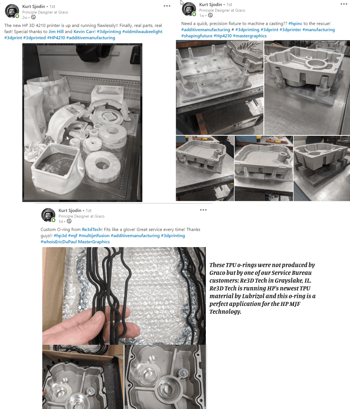
Topics: 3D Printing

How the HP Multi Jet Fusion 4200 Works

By Mark Blumreiter on Nov 13, 2019 11:55:38 AM

MasterGraphics Additive Manufacturing Engineer, Mark Blumreiter explains how the MJF works and how this technology is different from other similar 3D Printer technologies.

Topics: 3D Printing
1 min read

3D Printed Robotic Arm Grippers

By Mark Blumreiter on Nov 12, 2019 1:16:43 PM


The final application we’ll look at for fiber reinforced 3d printed parts is robotic arm grippers. Any tool at the end of a robotic arm benefits from being lightweight because it requires less energy to move the arm. The grippers also need to be strong and stiff enough to handle the stresses involved with lifting, assembling, or machining the component. Depending on the part that’s being gripped, the grippers sometimes require unique geometry. For these reasons, 3D printed fiber reinforced are the perfect solution.

A U.S. based fittings and valves manufacturer fully embraced the Markforged 3D print technology in their shop. Their engineers used to spend days or weeks tooling up a robotic work cell with custom machined grippers and fittings. Now they can re-tool the robot grippers in less than 24 hours.

End of Arm Gripper

robotic end of arm gripper


Topics: 3D Printing
1 min read

3D Printed End-of-Arm Vacuum Tooling

By Mark Blumreiter on Nov 12, 2019 1:04:57 PM


Another great example of reinforced 3D printed parts on the shop floor is end-of-arm vacuum tooling. When lightweight, flat parts need to be moved around and assembled, it’s common to use vacuum tooling to use air and suction parts to hold and move them. The image below shows a blue tube that is pulling air through the black tool. This creates the suction necessary to lift and move these lightweight parts.

3D printed end of arm tooling

There are a handful of properties these vacuum tools can require that 3D printing excels at. First, the tool should be lightweight because it is attached to the end of a robotic arm. Second the air suction needs to be routed through internal channels to provide suction at multiple locations. Finally, the tool needs to fit a unique contour of the part it’s picking up. Fiber reinforced 3D printed parts are the perfect solution for strong, stiff, lightweight, custom geometry vacuum tooling.

Keep in mind, these vacuum tools are typically only needed in very low quantities (1-10 parts) which is perfect for additive manufacturing. There’s no need to book time on a CNC mill and fixture an aluminum block for machining. This makes it much quicker to iterate new designs as well.

Using data from another Markforged case study, these numbers show the difference between aluminum and fiber reinforced vacuum tooling.

Part Comparison

vacuum tooling


Topics: 3D Printing
1 min read

CMM Fixtures

By Mark Blumreiter on Nov 12, 2019 12:53:55 PM


CMM fixtures are used to hold parts in place as they are being measured by a CMM. These measurements help ensure the manufacturing process is working as planned, and parts are meeting their dimensional specs. The traditional way parts are held in place for measurement is a combination of clamps, posts, and stops. But with composite reinforced 3D printed fixtures, we can create a lightweight, sturdy, more functional fixture suited precisely for your part.

The below graphic shows real data is from a Markforged case study regarding a US aerospace company.

CMM-1

The reason these time and cost savings could be realized in the first place was because the 3D printed CMM fixture actually worked. This can’t be said for all 3D printed parts. In fact, many other 3DP materials would not meet the strength and stiffness requirements while still providing the cost savings. The Markforged fiber reinforced Onyx parts also provided a non-marring surface for the aerospace components to sit in. This helped prevent the occasional scratched part.

Engineers at this aerospace company had been looking for ways to avoid bottlenecks like CMM fixtures. Once they discovered the fiber reinforced 3D printed parts as a functional, cost effective alternative, they haven’t looked back.


Topics: 3D Printing
1 min read

3D Printed Carbon Fiber on the Shop Floor

By Mark Blumreiter on Nov 12, 2019 11:46:39 AM

3d parts on the shop floor

In the past few years, composite 3D printing has officially hit the main stage. Companies like Markforged, EnvisionTEC, Cosine, and 3Dynamics are looking beyond traditional plastic extrusion machine capabilities and incorporating new materials such as carbon fiber, Kevlar, fiberglass, and ceramics. Combining these traditional fiber and ceramic materials with a proven additive technology creates a reliable and cost effective way to 3D print strong, durable parts for the shop floor.

The primary applications for fiber reinforced 3D printed parts on the shop floor include fixtures, jigs, tooling, and grippers; all of which can benefit from complex geometry and lightweight designs. This is where additive manufacturing excels. Anyone who is familiar with 3D printers knows that complexity is free.

The freedom to explore new design choices and 3D print truly functional parts for the shop floor can be a big time and money saver. Let’s look at a real world examples, 

Ready to get started printing on your shop floor? Lease a Markforged Mark Two for $449 per month.
Topics: 3D Printing
2 min read

What is an HP DFAM event? Should you attend?

By Jim Hill on Oct 2, 2019 12:26:12 PM

Not only is HP changing Additive Manufacturing with their print technology but also in their approach to advance the utilization of 3D print within manufacturing.  HP has a unique perspective since they have built their reputation on top quality and innovative equipment and they are sharing their knowledge on how to leverage 3D print from design all the way to manufacturing.  This series is designed to help companies understand how they can move from prototyping to production using 3D print.  HP currently uses Additive Manufacturing to produce final use parts and have cost justified and proven out the economics.  It must also be noted, after I have attended a number of these sessions, the concepts and training provided are applicable to other 3D print technologies such as SLS and Carbon.  I assure you it’s truly a great educational session.  


Click the link below to watch this YouTube video on what DFAM is.

https://youtu.be/uBBxGiBI6qU

dfam

Some highlights of what you will learn:

  • How and why HP decided to leverage MJF 3D printing technology to manufacture over 140 function parts used in each of our new MJF 500/300 series 3D printers vs. injection molding.
  • How to identify and select the right applications for additive manufacturing across your product lifecycle.
  • Training on the fundamentals of effective design for MJF.
  • How the process works and design strategies for MJF process optimization.
  • How the materials behave and what to consider when designing for each of them.
  • The new design paradigms that are enabled by additive manufacturing and the required mindset change.
  • How to design for value maximization (process and cost).
  • Training on the fundamentals of effective design for MJF.
  • Live Design for Additive Manufacturing (DfAM) demo and application examples to inspire you.

You are always welcome to stay after the scheduled presentations and discussions to consult with technical experts from HP 3D Printing on your own parts.   That could be the most valuable part of the session is the post conversation on your specific challenges and if 3D print makes sense to utilize. 

Feel free to reach out to me to find the next HP DFAM event in your area.

Jim Hill
3D Account Manager
3701 Algonquin Rd, Ste 780
Rolling Meadows, IL 60008
847.704.4029 Direct
800.873.7238 Toll-free
JIm.hill@mastergraphics.com
www.mastergraphics.com


Topics: 3D Printing
5 min read

Comparing HP’s 4200 Multi Jet Fusion (MJF) printer to their 5200 Multi Jet Fusion Printer (MJF)

By Kevin Carr on Oct 2, 2019 12:18:17 PM

HP recently announced the expansion of their Multi Jet Fusion (MJF) printer line up to include the new 5200 series.  This has created many questions around the difference between the recently announced 5200 and the existing 4200 since architecturally they look similar.  Let me take a quick step back and provide some background on the 4200 before I get into the differences.  HP launched their ground breaking 3D print technology (MJF) with the 4200 back in 2017.  The 4200 provided revolutionary 3D print technology that moved forward the ability to mass print plastic (PA12 at launch) parts at speeds, cost, and ease of use not seen before in additive manufacturing.  I describe MJF as Selective Laser Sintering (SLS) on steroids.  HP’s MJF technology truly changed the 3D print market and started a further shift from prototyping to manufacturing.  You can see how the 4200 built new service bureaus who grew based on HP’s technologies and how companies now manufacture truly use parts from the 4200 as final parts.  Here are some of those service bureaus who have grown substantially due to HP. 

re3dtech            forcast3d     fast radius

Personally in my 12 years spent within 3D printing, I have not seen any other technology change the 3D print landscape like the 4200.   The 4200 met its promise to bring Additive Manufacturing to the masses.  Earlier this year, HP started shipping the 500 series that added the ability to print color but lacked the throughput of the 4200.  The differentiation between the 500 series and the 4200 was clear.

Now to the introduction of the 5200, how does this fit in the evolution of HP’s technology? The 5200 does not replace the 4200.  The 4200 will stay as a production unit and still provides manufacturing capability.  The 5200 is the next step forward to increase throughput and most importantly provides tools and processes for manufacturers to replicate the manufacturing standards and processes they currently use in production.  It has more advanced software when compared to the 4200 and provides a feedback loop to allow even better control of output quality.  The 5200 is sold at a premium price so depending on your needs, the 4200 still may be a fit. 

hp 5200

Here is an outline of some of the key advancements now offered with the 5200 versus the 4200.  Keep in mind the goal of the 5200 is to bring true manufacturing predictability and standards to Additive Manufacturing and provide even faster throughput.

Breakthrough Economics vs the 4200

Up to a 30% cost per part savings due to multiple machine advancements including:

  • One pass printing (versus two on the 4200) resulting in up to 50% less agent consumption
  • Shorter routine on print head wipes needed as part of the print process
  • 4x longer cleaning roll for better cost efficiency

Improved throughput

Warm up time cut in half versus the 4200

  • Faster print times: 5200 in balanced build mode finishes a full build in 11.5 hours compared to 14 hours by the 4200 in balanced mode.
  • Enabled via 1 pass printing vs 2 passes- creating the true ability to get two full builds in 24 hours
  • Fast build mode reduced to 9 hours from 11.5 hours versus 4200.

Manufacturing standards and controls designed into the printer and software.

  • The 5200 has the capability to reach a Cpk of 1.33 on an IT scale of 13. Process capability index (Cpk) is a statistical tool, to measure the ability of a process to produce output within customer’s specification limits. In simple words, it measures producer’s capability to produce a product within customer’s tolerance range. Cpk of 1.33 equals a process yield of 99.99%
  • The new Process Control Center software focuses on calibrating Z dimensional accuracy for improved accuracy and repeatability to achieve more accurate output.
  • Production software is enabled on the 5200, it uses data feedback from the printer to adjust settings and learn as it prints to improve accuracy and reliability based on the advanced sensor built into the 5200.
  • Improved Heating control: the 5200 now has 22 lamps with 14 zones of control (compared to 20 lamps with 12 zones of control on the 4200) – 5X better thermal camera and improved data feedback to measure more minute heating variations, and therefore provide more precise heating adjustments.

Screenshot of the Process Control Center

3d process control

There are some significant hardware differences to improve manufacturability:

  • Better cooling of the print heads to eliminate print failures
  • Improved Lamp control: The lamps are now engineered to only use about 50% of their capability which allows improved reliability and the printer can now more easily “throttle up” or “throttle down” the lamp control (in smaller increments) to more precisely control the heat to specific areas of the print bed based on the improved thermal readings from the thermal camera.
  • Lamps will now always stay “on” thus allowing for longer lamp life eliminating the cycling of on/off that would reduce lamp life
  • Smaller micron layers than the 4200 – now 110 micron layers
  • Semi-Automated Printhead alignment: This new process assures X&Y dimensional accuracy
  • There have also been improvements in airflow via better seals, fans, and flow-through (via a 2nd “Lung” on top left of machine)
  • Machine now has fans & sensors to mitigate against suction/pressure variations created at customer site

New materials support

  • Machine designed to support materials up to 225C which enables a larger breadth of material possibilities
  • Build unit designed to work with lower flow type materials
  • There are redesigned ramps for the material to better flow inside the build unit
  • Processing station redesigned to be able to unpack materials at higher temperatures
  • Ultrasonic sieve (in processing station) with a wider mesh thus enabling more versatility to supporting new materials
  • TPU Material available from BASF: BASF TPU01
Improved Post Processing
  • HP has developed specific natural cooling units to allow the cooling of builds without leaving them in the build carts.
  • As special Hovmand Forklift allows the moving of the cooling units from the build cart for improved productivity.

hp natural cooling

These are just some of the highlights.   I encourage you to look closer at the 5200 if you are looking to implement true additive manufacturing.  The 4200 still has a place in the prototype and production space but if you want to have a system designed for manufacturing with specific measurable standards in place, the 5200 is worth investigating. 

Feel free to contact me at Jim.Hill@mastergraphics.com or 847-704-4029

Email Jim


Topics: 3D Printing